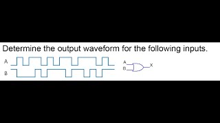
Media Summary: Hello. In this lesson you will learn about the Please like this video if you found it helpful. The figure shows a logic circuit with two
Or Gate Output Waveform Determine - Detailed Analysis & Overview
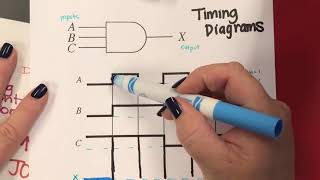
Hello. In this lesson you will learn about the Please like this video if you found it helpful. The figure shows a logic circuit with two This Digital Logic video is about how to draw timing diagrams from a given boolean expression and how to complete timing ...