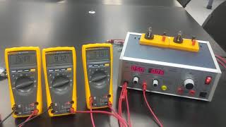
Media Summary: Series circuit of figure 3.6 showing the current and the voltages across BC, DE, and BE (from left to right). placing the ammeter in ... Parallel circuit of figure 3.7. the ammeter shown here is connected between points A and B. the voltages from left to right are ... the ammeter is on the far right, and the voltmeters from left to right are measuring the voltages across R1, R2, and R3.
Phys 152l Lab 3 Activity - Detailed Analysis & Overview
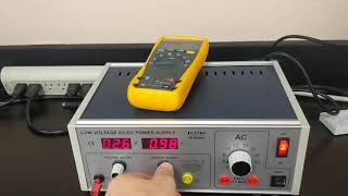
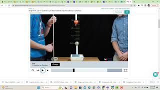
Series circuit of figure 3.6 showing the current and the voltages across BC, DE, and BE (from left to right). placing the ammeter in ... Parallel circuit of figure 3.7. the ammeter shown here is connected between points A and B. the voltages from left to right are ... the ammeter is on the far right, and the voltmeters from left to right are measuring the voltages across R1, R2, and R3. measurement of resistance between A and B in figure 3.8. from left to right, the measured values of R1, R2, and R3. 102 g masses are placed at 0.0, 100.0, and 145.0 degrees. The equilibrant force direction can be found from the video, and the ...
parallel circuit of figure 3.9. the ammeters are reading (from left to right) the currents in R1, R2, R3, then the total (the ammeter next ... 1.00 N forces are placed at 0.0 and 90.0 degrees. The equilibrant force direction can be found from the video, and the mass ... 1.00 N forces are placed at 0.0 degrees and 135.0 degrees. The equilibrant force direction can be found from the video, and the ... Here the current is varied while the length remains fixed. The relevant data can be collected from the video. PHYS 151L, Lab 4, activity 1, measurement 3